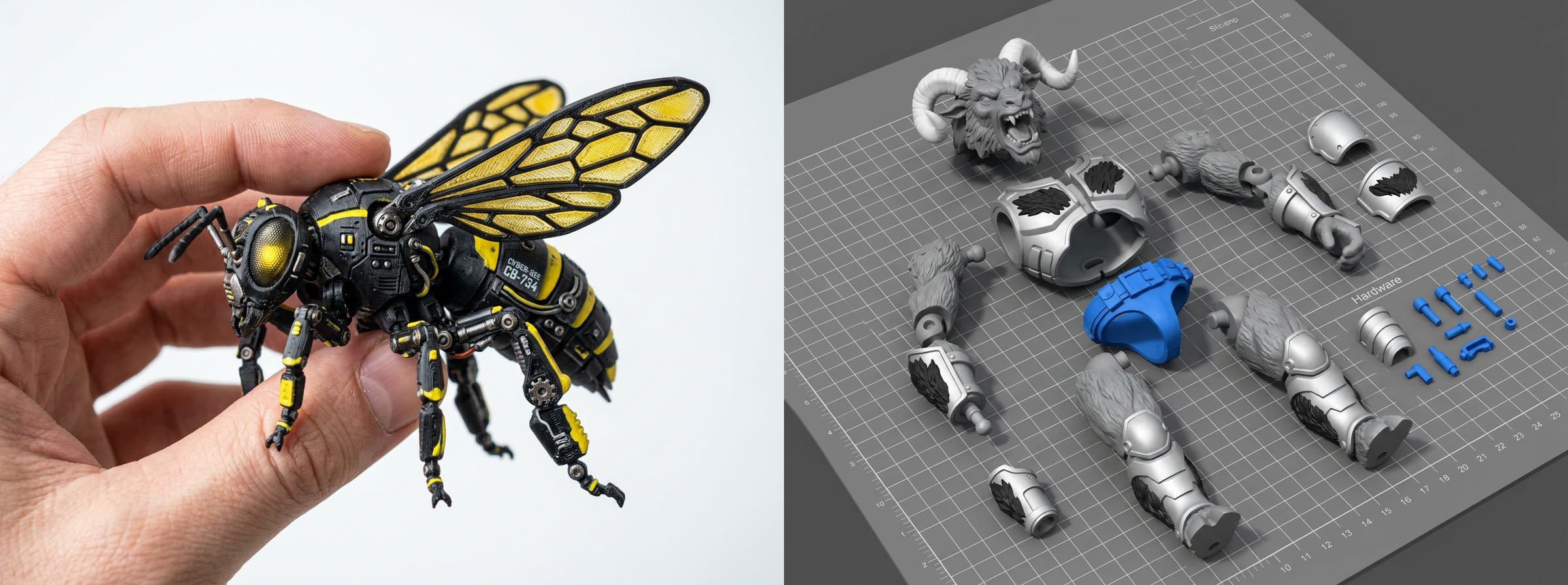
Split models with ease. Auto-generate connectors. One-stop pre-processing for 3D printing. Beginner-friendly. Fast. Easy.
| Scenario | Applicable Models | Key Features | Recommended Users |
|---|---|---|---|
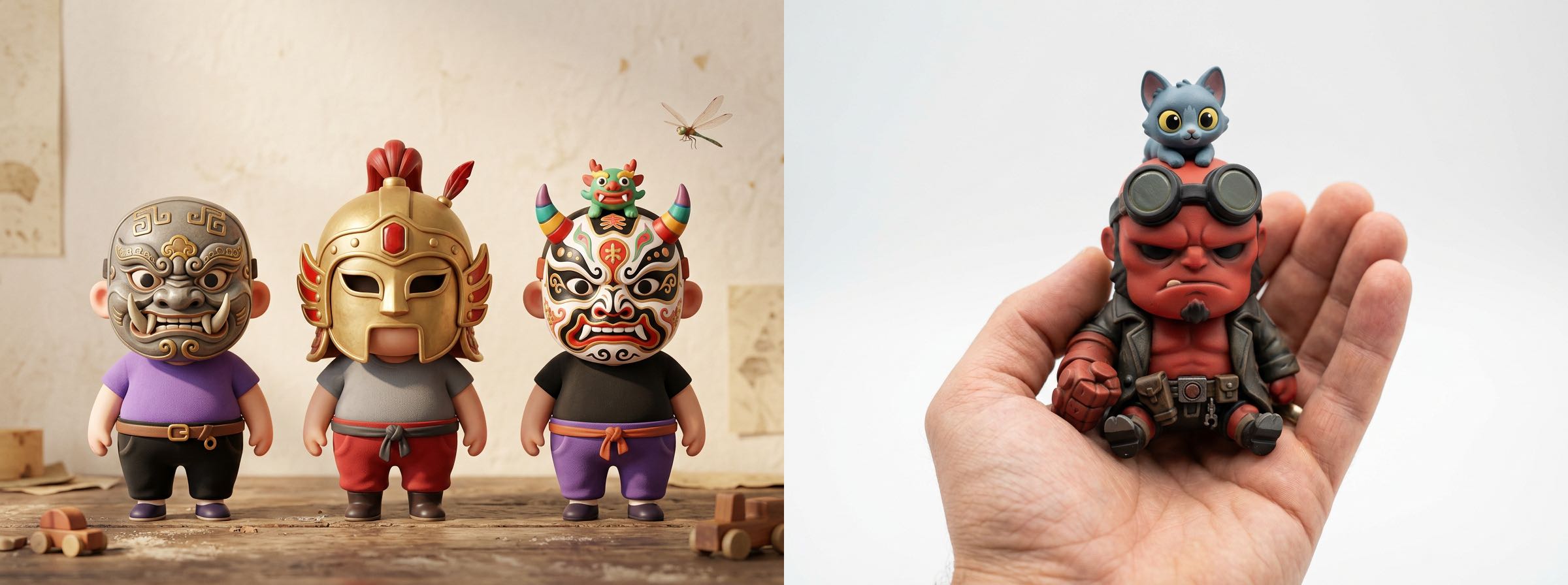
| Character & Scene | Figurines, action figures, character models | Preset splitting templates, one-click connector generation | Beginners, quick printing & assembly |
| General Purpose | Buildings, weapons, machinery, vehicles | Supports custom splitting/merging, flexible and controllable | Advanced users, complex model customization |
I. Character & Scene Tutorial (Figurines / Action Figures)
Ideal for humanoid models. Supports one-click part splitting + connector generation. Extremely simple workflow.
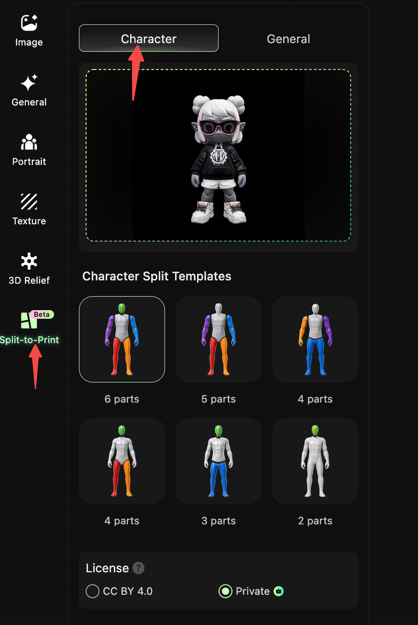
Step 1: Enter Character Splitting Interface
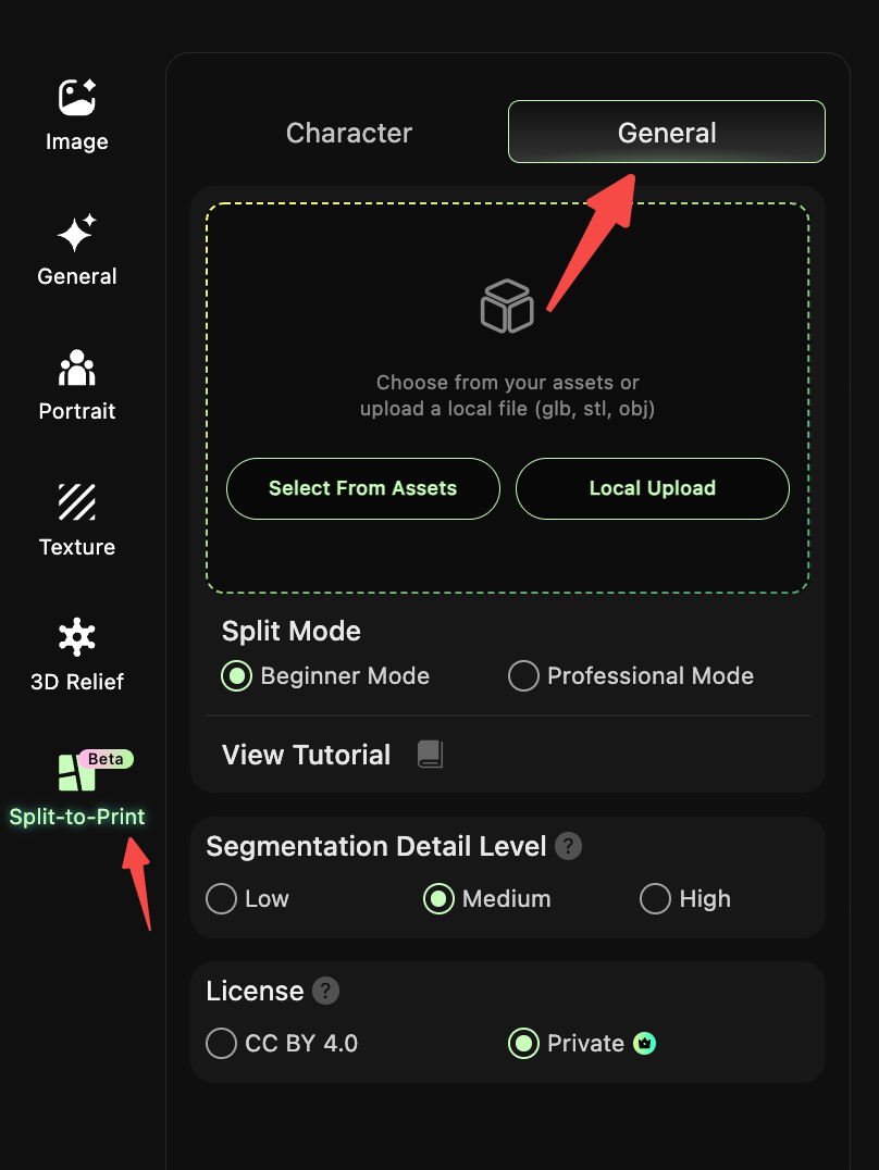
- Open the HI3D Workbench and click “Split for Printing (Beta)” in the left navigation bar.
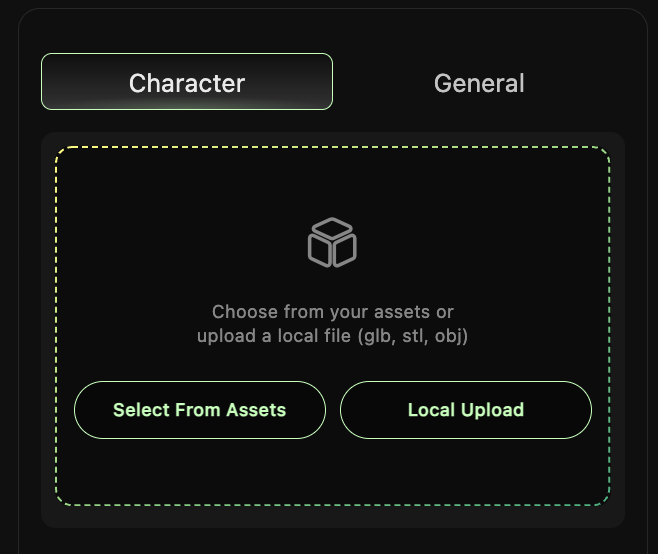
- Select the “Character” tab at the top to enter the character model splitting interface.
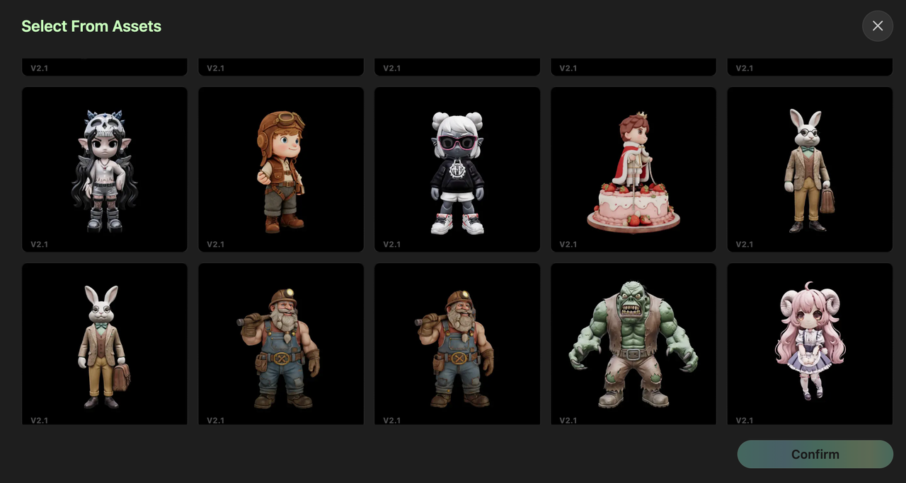
Step 2: Upload / Select Target Model
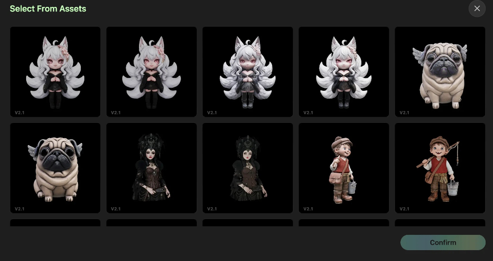
- Click “Select from Assets” to choose an existing character model, or click “Local Upload” to upload a local model file in GLB, STL, or OBJ format.
- Once the model is uploaded, the preview area on the right will display the model.
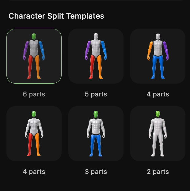
Step 3: Select Splitting Template
In the “Character Splitting Template” section, choose the splitting granularity based on your printing needs:
- Template Options: 2 / 3 / 4 / 5 / 6 parts (more parts = finer splitting, suitable for larger print sizes or more detailed models).
- Template Preview: Each template comes with a preset humanoid splitting logic (e.g., head / torso / limbs split). Click to preview the splitting result.
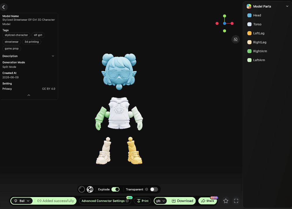
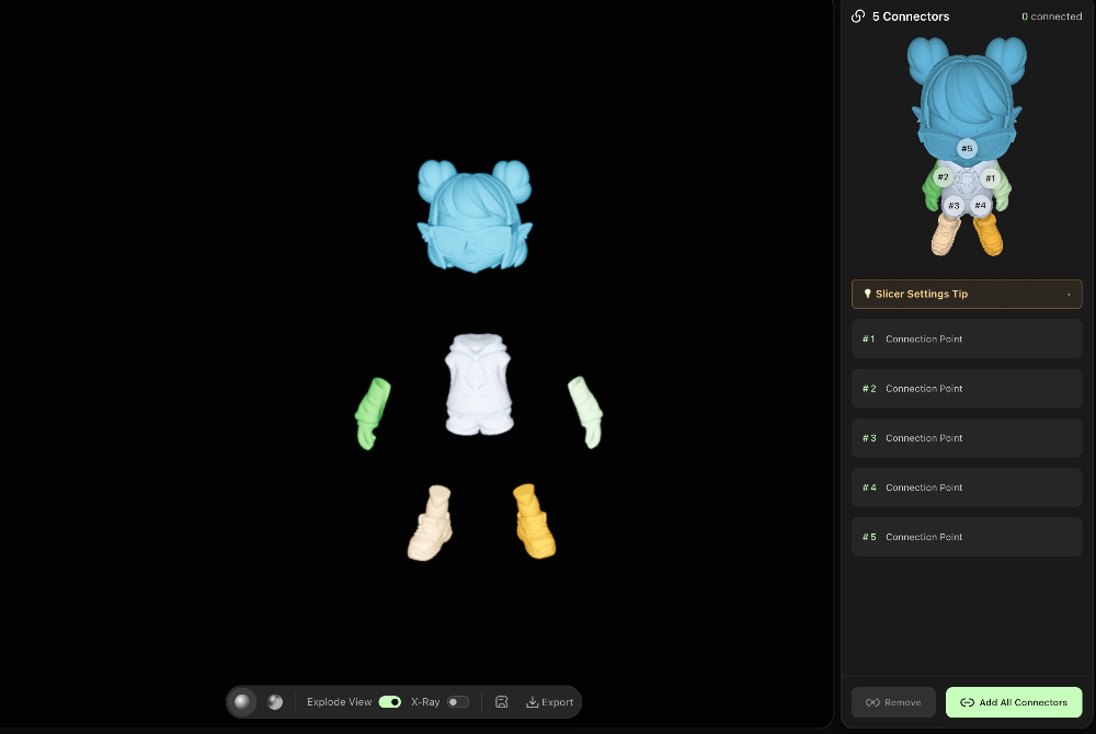
Step 4: One-Click Connector Generation
- After confirming the splitting template, the system automatically splits the model and performs watertight sealing.
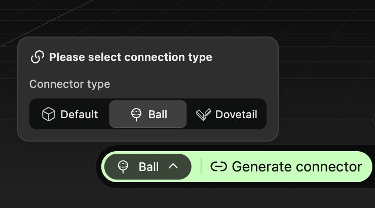
- Click “One-Click Add Connectors” – the system will automatically generate connectors for the split parts. Three connector types are available:
- Mortise & Tenon Joint: Suitable for static figurines – sturdy assembly with no movement.
- Ball Joint: Suitable for action figures – supports multi-directional posing.
- Rivet Joint: Suitable for single-direction movable parts (e.g., arms, legs).
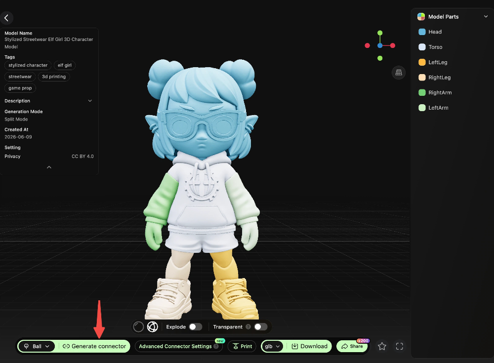
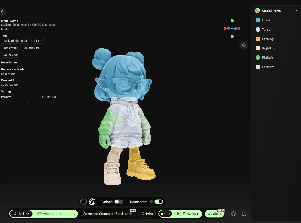
- Preview the connector result. Once confirmed, export the model file for printing.
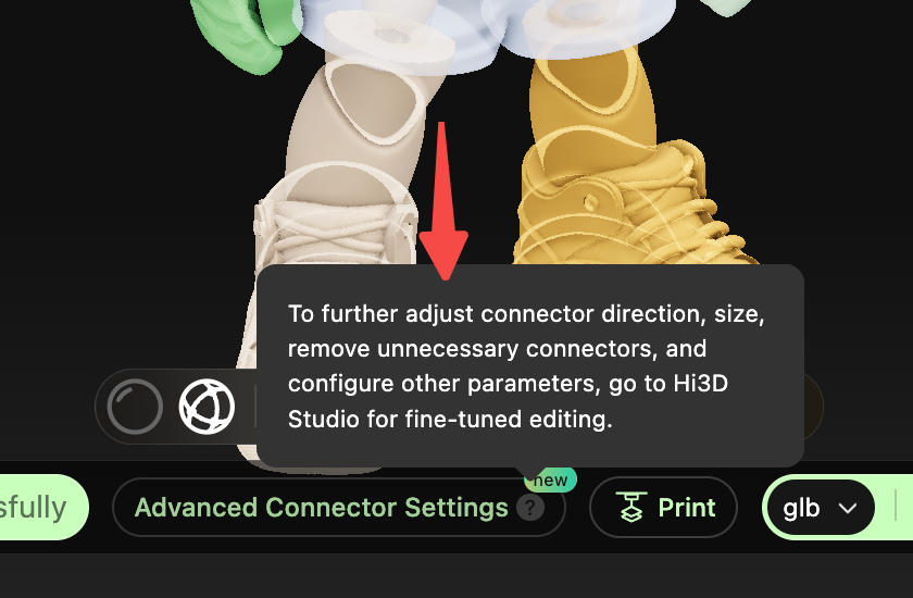
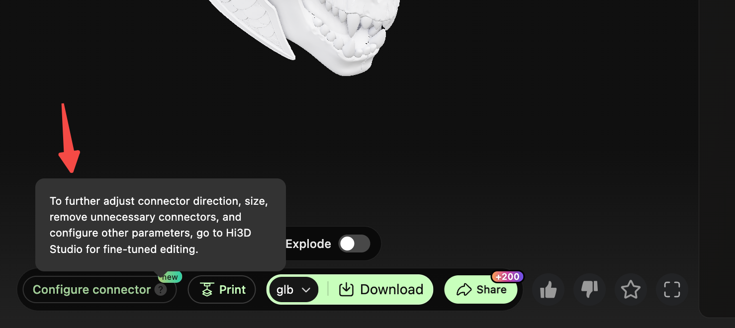
Advanced Tip: Fine-Tuning in Studio
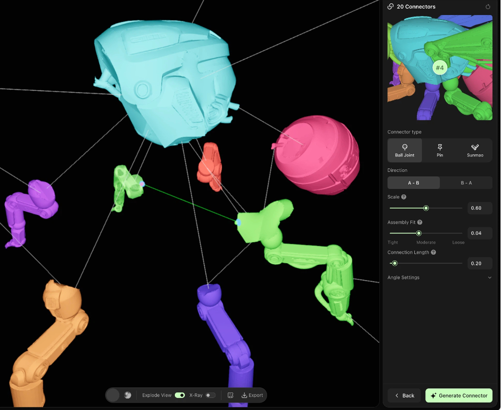
If the automatically generated connector orientation or position is not ideal (e.g., incorrect connection point, alignment offset), click “Go to Studio to Add Connectors” to enter the Studio interface. There you can manually adjust connector positions, modify connector types or parameters, and achieve more precise customization.
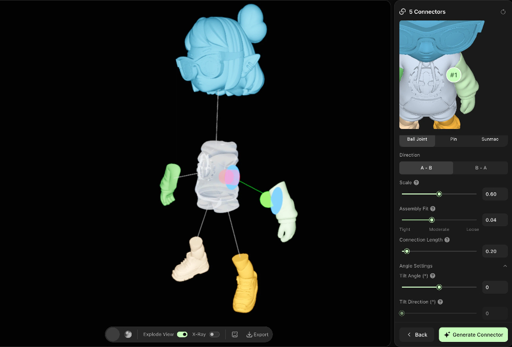
- Size: Scales the connector overall. 0.6 = connector diameter matches the auxiliary surface diameter (default). Increase to make the connector stronger/beefier, but ensure it does not exceed the part boundaries.
- Assembly Tightness: The fit tightness between the male and female parts (bilateral gap). Increasing → looser assembly, smoother movement but easier to come apart. Decreasing → tighter assembly, but may get stuck or be difficult to insert. Recommended range: 0.02 – 0.1.
- Connection Length: Neck length of the ball connector (distance from the ball center to the part surface). Increasing allows it to reach deeper into the mating part, strengthening the connection.
- Tilt Angle: The angle by which the connector tilts around the “insertion direction” (0–45°). Used for angled/sloped surface connections: adjust the connector axis to make it perpendicular to the actual mating surface, ensuring proper assembly after printing. 0 = along the default normal direction (legacy behavior).
- Tilt Direction: The azimuth/orientation of the tilt (rotate around the “insertion direction” to choose which side to tilt toward). 0–360° covers all directions. Only effective when Tilt Angle > 0.
II. General Purpose Tutorial (Architecture / Machinery / Non-Humanoid Models)
Suitable for models without fixed structural semantics. Supports custom splitting and mesh editing for greater flexibility.
Step 1: Enter General Purpose Splitting Interface
- Open the HI3D Workbench and click “Split for Printing (Beta)” in the left navigation bar.
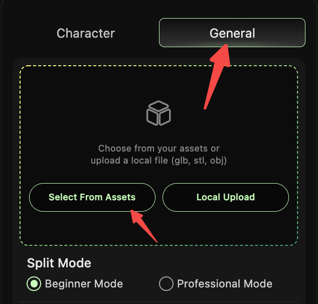
- Select the “General” tab at the top to enter the general model splitting interface.
Step 2: Upload / Select Target Model
- Click “Select from Assets” or “Local Upload” to import the target model (supports GLB/STL/OBJ formats).
- The preview area on the right will display the model.
Step 3: Select Splitting Mode & Parameters
Mode 1: Beginner Mode (Newbie-Friendly)
- Select “Beginner Mode” and set the “Splitting Granularity” (Low / Medium / High — higher granularity means finer splits).
- The system automatically splits the model — no manual operation required.
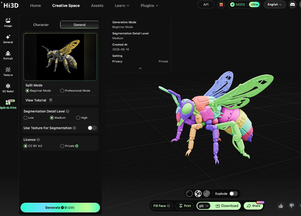
Mode 2: Professional Mode (Custom Splitting)
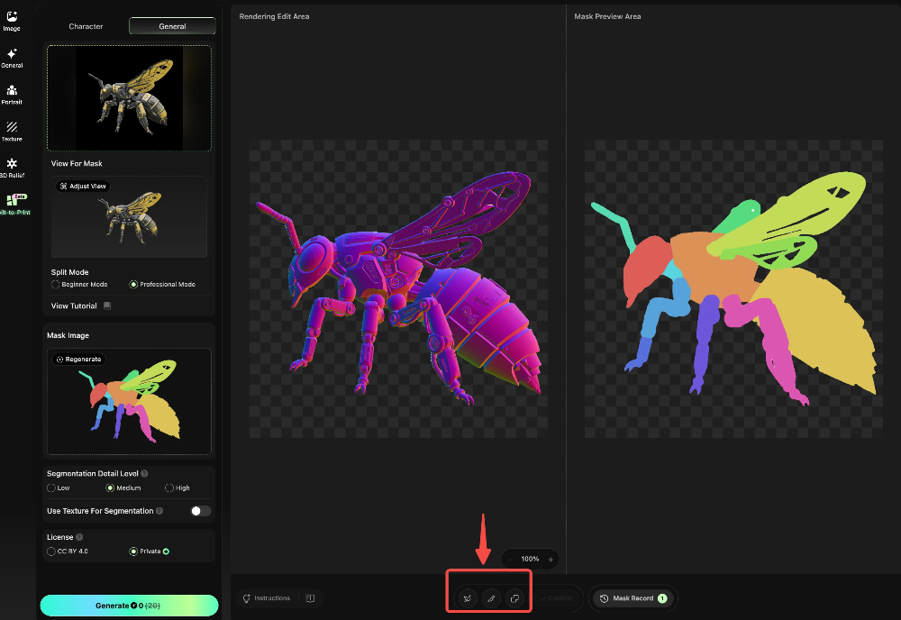
- Select “Professional Mode” and set the “Splitting Granularity”. Then you can manually:
- “Lasso” : Custom select splitting regions.
- “Merge” : Combine multiple automatically split meshes into one part.
- “Split” : Further split existing parts to meet specific printing or assembly requirements.
Step 4: Mesh Adjustment & Watertight Sealing
- After splitting is complete, adjust the meshes based on assembly needs: merge unwanted split meshes, refine part boundaries.
- The system automatically performs watertight sealing to ensure the model has no holes or errors and is ready for printing.
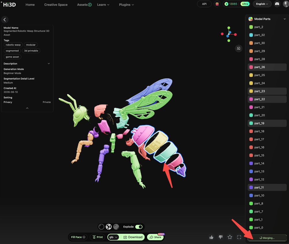
![merge-meshes-after-auto-split]](/images/pasted-1033.png)
Step 5: Generate Connectors in Studio
Click “Go to Studio to Add Connectors” to enter the Studio interface:
- Add connectors (Mortise & Tenon / Rivet / Ball Joint) to the split parts.
- Manually adjust connector positions and orientations, and correct algorithm-misjudged connection points (e.g., redundant connectors, incorrectly connected parts).
- Once the result is confirmed, export the model file — ready for printing and assembly.
III. Application Scenarios & Advantages of the Three Connector Types
Mortise & Tenon
- Features: Traditional interlocking structure. Fixed and rigid after assembly. Strong and durable.
- Applicable Scenarios: Static figurines, display models, fixed-pose works.
Ball Joint
- Features: Multi-directional movement, supports free posing, highest flexibility.
- Applicable Scenarios: Action figures, jointed toys, models that require adjustable poses.
Rivet Joint
- Features: Cylindrical single-axis connection. Rotates in one direction. Stable structure.
- Applicable Scenarios: Single-direction movable parts such as arms/legs, simple poseable models.
IV. FAQ & Troubleshooting Guide
1. Why can’t I manually merge meshes in Character & Scene mode?
The splitting templates in Character & Scene mode rely on humanoid structural semantics. Merging meshes would disrupt the preset connector point layout and affect connector generation. Therefore, a “template-as-result” streamlined process is adopted. For custom splitting, switch to General Purpose mode.
2. After one-click splitting in General Purpose mode, there are too many parts. What can I do?
Use the “Merge” function in Professional Mode to combine meshes that belong to the same printing/assembly unit into one part, reducing the number of printed pieces.
3. How to fix connector generation errors (e.g., wrong orientation, missing connection points)?
Simply jump to the Studio interface and manually adjust connector positions and modify connector types. Studio supports fine-grained editing of all connection points to resolve algorithm misjudgments.
4. What if watertight sealing fails?
Check if the model has holes or non-manifold edges. Repair the model in Studio first, then regenerate connectors. Alternatively, lower the splitting granularity to reduce the chance of mesh errors.
V. Complete Workflow Summary
HI3D integrates all the features creators need throughout the entire process, with seamless connection between each step. The complete workflow is:
Inspiration & Creation (Text-to-Image / Image Editing / Auto Multi-View Generation) → Model Generation (General / Portrait / Relief) → Post-Processing (Model Editor / Split for Printing / Connector Generation) → One-Click Print